The Nerve Suit
a wearable LED / fiber optic pieceby Tim Vogt
What is the Nerve Suit?
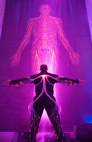
The Nerve Suit is a dynamic fiber optic and LED suit modeled after the human nervous system. The fiber optic nerves pulse and change colors in fixed patterns, random patterns, and patterns based on audio input, all under control of a microcontroller. Each arm, leg, and the torso has 5 independent segments of optical fiber bundles, which, when lit in sequence, look like nerve impulses traveling down the spine through the body. Each of the segments (25 total) can independently glow in any one of 4096 colors.
Why Build a Nerve Suit?
I've worked on many large-scale Burning Man projects over the years (Omphaloskepsis Camp, L2K, Ship to Ship, Optical Acoustics, L3K, etc.) as a member of the Mad Scientists Collective, but in 2005 I decided to do a "small" personal project instead. Little did I know it would take just as much work (if not more) than any of those big projects. Because unlike those projects, on this project I did almost everything myself--conceptual design, hardware, software, construction, etc.
I've been attending Burning Man since 1997, and I've watched the evolution of EL-wire and LED pieces, from the early days of the horse galloping across the playa in 1998 (one of my all-time favorites), to L2K, to the LED wall, to (more recently) L3K and the Cubatron. When I started brainstorming for my own project, I decided that I wanted to do something different, something I hadn't seen before. And the more I thought about it, the more I realized that I had not seen optical fiber used in any serious way. So, I did a lot of brainstorming to figure out what I could do in this new medium, and it finally hit me--nerve impulses. Once the idea struck, it planted itself deep in my brain and refused to budge until I had finally built it. I'm happy to say that the final result exceeded my expectations.
Constructing the Nerve Suit
Building the Nerve Suit was at least a 6-month process from conception to completion. The first step was to experiment with different types of fiber to see which would give the desired effect. I bought a sampler of various fiber sizes and played with them using LEDs, cut the fibers into bundles, etc. The 0.5mm plastic fiber seemed to work the best, visible and easy to work with but not too fine, so I ordered a 6km (3.7 mile) spool.
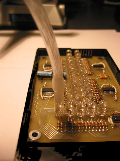
The next step was to design the circuit boards. After surfing the net quite a bit for LED controllers that had programmable intensity, I came across a family of Maxim ICs that fit the bill, and selected the MAX7313. The MAX7313 uses PWM running at 32kHz to control LED intensity at up to 14 intensity steps per channel, for up to 16 channels. I decided to use 15 channels, driving 5 RGB LEDs with each MAX7313. The LED controller board has 5 MAX7313's, one for each arm, leg and torso. Each MAX7313 drives 5 RGB LEDs, so that each appendage has 5 segments of fiber. The first prototype board had the wrong LED hole spacing, so I had to build a second one. In the end, it looked like this:
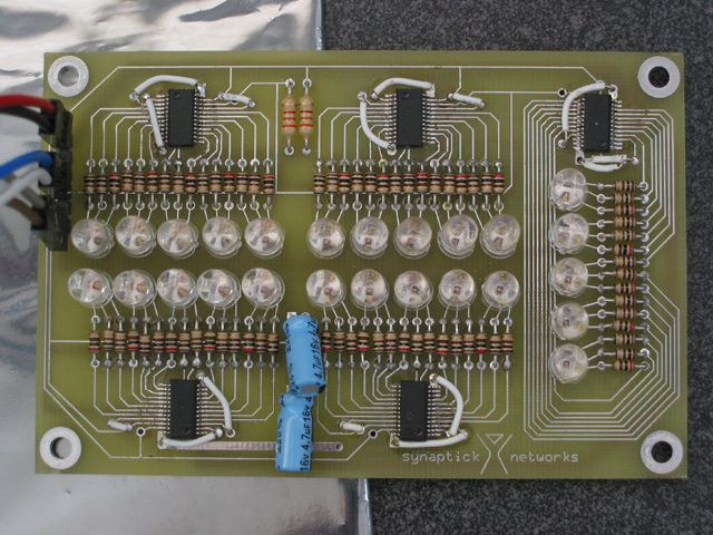
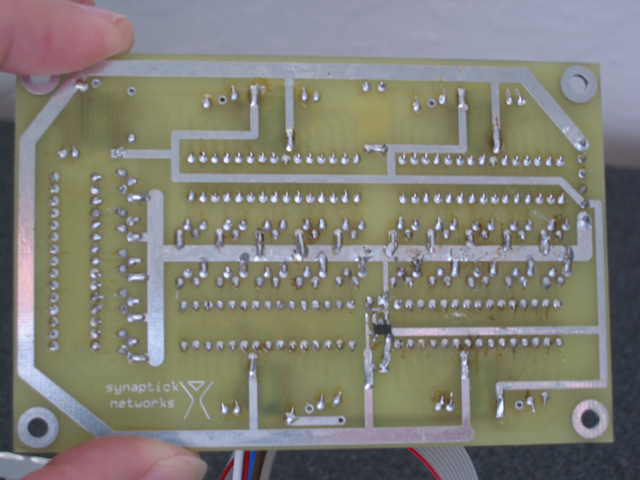
The design was pretty simple and clean. I decided to use through-hole resistors because 1) the resistor packs wouldn't have saved any space (LED placement and chip routing were the main area constraints), 2) I had a lot them lying around, 3) and they're easy to solder. The jumper wires are there to select different I2C addresses for the LED controllers.
The next step was to write the software to talk to the LED controller board over I2C. This was a lot harder than I anticipated. I ended up writing my own I2C driver for the Atmel TWI hardware (similar to some code on the Atmel website, but written mostly from scratch), and doing a fair amount of experimenting to figure out how to program the MAX7313's to do what I wanted. But in the end, I got it working.
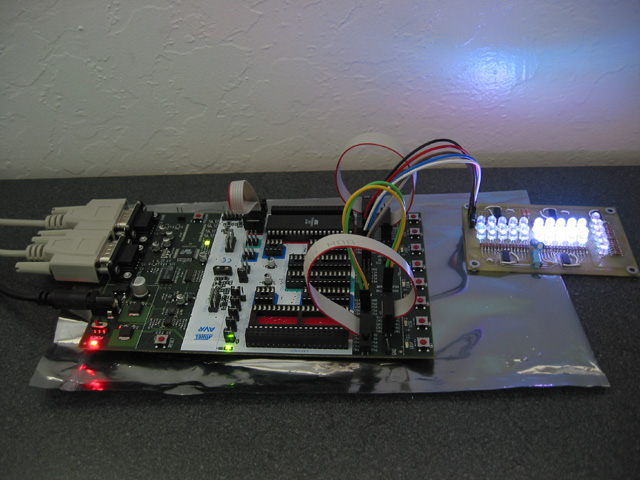
After I got it working, I designed a small board for the Atmel ATMega32L to run the main control program. I probably could have bought a generic Atmel development board instead, but it was good practice to design my own, and I was able to make it very small. The control box, with buttons, switches, and jacks, fits inside my pocket.
To add audio input, I used a trick I learned from Tim Black. I simply bought a Voice Activated LED Kit from Jameco and tapped off one of the LED output lines, which just so happens to run at TTL logic levels. I ran this signal into a GPIO pin on the ATMega32L, and in the software I sampled this line periodically, increasing a counter when it's 1 and decreasing the counter when it's 0. This gives a rough audio level measurement, which is good enough to do audio-sensitive light patterns. See below for some video clips of the audio-sensitive mode in action.
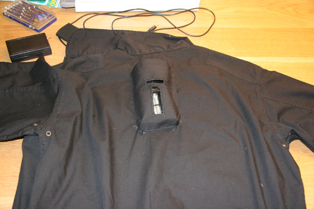
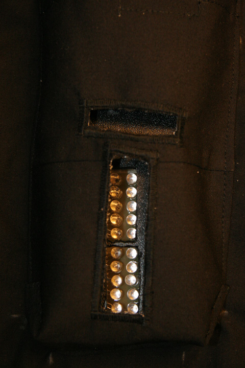
With the electronics done, it was time to turn my attention to the suit itself. First, I searched around for suitable costumes/clothing to use as a base. I wanted something relatively form-fitting, but easy to put on and take off, and easy to work with. In the end, I decided to go with a black flight suit from Mountain View Surplus. It met all of my criteria, plus it had pockets, which are always handy. Then, the only modification I needed to do to the suit itself was to create a pocket on the back for the LED controller board. Using donor material from inside one of the pockets, my sister-in-law helped me sew on a patch pocket between the shoulders, with cutouts for the LEDs.
The bulk of my time on this project was spent experimenting with different optical fiber construction techniques, in particular, 1) how to attach bundles of fiber to the LEDs and 2) how to attach fiber to the flight suit. My best discovery during the experimentation process was that clear plastic drinking straws from Mr. Chau's Chinese Fast Food are the exact right size to snugly fit over a 5mm LED. I'm sure other straws will work, but these were the best I found from local establishments. After a fair amount of experimentation, I created a technique using straws, hotglue, and a sharp knife to create a connector for bundles of fiber to the LEDs.
This connector works fairly well, but I've found over time that it could use some improvement. The straw is a snug fit, but it does tend to pull off the LED more easily than I would like. And when you go to re-plug in the bundle, the straw is a little weak and will bend/crush if you don't line it up just right on the LED. Things to think about for the next revision. :-)
Attaching the fiber to the suit took quite a bit of experimentation as well. I ended up using a combination of techniques: sections of drinking straws for large bundles (safety-pinned onto the flight suit), the Buttoneer, and fabric glue. The Buttoneer was recommended to me by Janet Hansen of enlighted.com, who makes illuminated clothing for a living. It's a device "as seen on TV" which puts little plastic staples through fabric; it's normally used to reattach buttons, but it worked great for attaching smaller bundles of fibers.
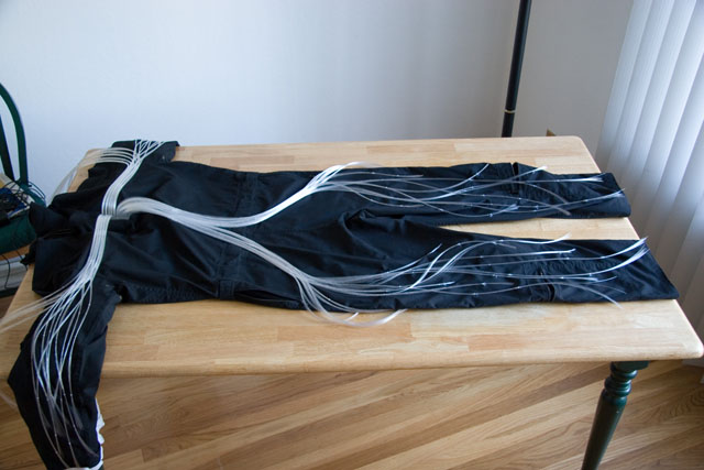
I laid out all of the fiber bundles into a pattern pleasing to my eyes, and left everything loose at first. After I put on the suit and put it through lots of bending motions to get enough slack in the fiber, I used fabric glue on the Buttoneer staples to tack down the ends of the bundles. The rest of the staples and the straws were left loose, to accommodate movement in the suit. The fabric glue dries clear, so you'd never know it's there unless you look closely.
The very last step was the software. As usual, the software wasn't finished until the last night before Burning Man. It wasn't pretty, but it worked. I have since cleaned up the code a bit and added some new sequences and controls, so it's even cooler than before. There's plenty of code space left in the ATMega32L, so I can add even more stuff if the mood strikes me down the road.
My favorite part of the testing process was tuning the audio input, cranking up the techno music and watching the suit pulse along with it. Here are a few video clips of the audio testing process:
If you want to download these video clips, here are the direct
links:
Audio Test 1
Audio Test 2
Audio
Test 3
Audio Test 4
I also managed to get some photos and video at Burning Man 2006, thanks to Komega (Craig Dorety).
If you have questions, or would like to see the schematics, board layout, or software for this project, please drop me a line. I'd be happy to share them with you.
--Tim Vogt
<myfirstname>@synaptick.net
May 2008
Nerve Suit Technical Highlights
| Part | Description | Quantity |
| microcontroller | Atmel ATmega32L | 1 |
| LED controller | Maxim MAX7313 | 5 |
| LED | 5mm superbright RGB | 25 x RGB (75 LEDs total) |
| optical fiber | 0.5mm diameter, plastic | ~1 mile |
| audio input | voice activated LED kit (Jameco) | 1 |
| power source | AA batteries (rechargeable, good for ~3 hrs) | 4 |
Resources
Here are some of the resources I found useful for parts and services while building this project:
Fiber Optic Products - bulk optical fiber, various fiber optics supplies
SuperBrightLEDs - LEDs
ExpressPCB - prototype circuit boards
Digi-Key - circuit components, misc. parts
Mouser - circuit components, misc. parts
Maxim IC - LED controller ICs
JoAnn Fabrics - sewing supplies
Mountain View Surplus - flight suit
Mr. Chau's Chinese Fast Food - clear plastic straws
Other Links
Enlighted - illuminated clothing
Moritex USA - optical fiber
WieDaMark - various lighting systems, including optical fiber
Luminex Idea - fabrics with optical fiber woven in
Michael's Light Toys - EL-wire, blinkies
Cool Neon - EL-wire